Best way to power Tapo C530WC (9V 0.85A, 5.5×2.1mm) over 20–30m cable run

xbn7

n3wb
Jun 29, 2026
4
3
Ukraine
Hi everyone,:thumb:
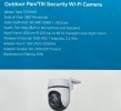
I’m planning to install a Tapo C530WC camera on a pole outdoors and I need to run power from a nearby outlet at a distance of around 20–30 meters.
I’m trying to find the most practical, reliable and cost-effective solution.

I already considered a few options:
  1. PoE setup
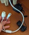
    I understand PoE would be the cleanest solution, but it requires a PoE injector + splitter (9v outdoor) + proper power conversion for this camera, so it becomes more complex and expensive than I would like.
  2. DC extension cable (5.5×2.1mm)
    This seems like the simplest approach, but I’m worried about voltage drop over 20–30 meters.
  3. Using thicker cable (DIY solution)
    I was thinking about using something like 2×0.75 mm² / 2×1.0 mm² / 2×1.5 mm² copper cable and attaching 5.5×2.1mm DC connectors on both ends (male/female adapters).
    Would this be a reliable and safe setup for continuous outdoor use over ~20 meters, or should I expect significant voltage drop or stability issues?
*WiFi is not an issue at this location (strong and stable signal), so the only real challenge is reliable long-distance power delivery.

What I’m trying to understand:
  • What AWG / cable thickness is realistically required for stable 9V/12V at ~20–30m?
  • Is a DC extension cable still reliable at this distance?
  • Is DIY thicker copper wire with DC connectors a valid professional approach or just a “hack”?
  • Has anyone here done a similar installation with the Tapo C500 / C510 / C520 / C530 series? I’m particularly interested in real-world, practical solutions — what you actually used and whether it’s been stable over time.

Thanks.
 

Attachments

  • dc222.jpg
    dc222.jpg
    93.3 KB · Views: 5
  • 332434324.jpg
    332434324.jpg
    114.7 KB · Views: 5
  • 2343242.jpg
    2343242.jpg
    69.1 KB · Views: 5
I agree that POE would be best but if you must go Wi-Fi:

The specs say that the camera draws .85 Amps, so I'd use no less than 1.0 Amps as a baseline. I also used the higher (30 meters) of your distance range of 20 to 30 meters. Lastly, I used 5% as an absolute maximum percentage of calculated voltage drop for the powered device at the load end of the run.

Using 3 separate online calculators, I find that you should use two #14AWG (2.08mm²) copper conductors to provide 1.0 Amps to a 9VDC device at the end of 30 meters and those conductors would allow less than 5% voltage drop.

EDIT: If you go this route be sure to use dielectric grease in/on the 9VDC connectors, test then wrap them with 2 layers of self-vulcanizing rubber tape and then 2 TIGHT layers of high quality vinyl electrical tape such as 3M #33+ or #88.
 
Last edited:
  • Like
Reactions: xbn7
My choice would be POE with 23 AWG solid copper ethernet cable, cat5e is fine. WIFI sucks for camera.

The only thing that worries me is that the TL-POE10R is rated for 0°C to 40°C. Mine would be installed outdoors in a weatherproof junction box mounted on a pole...
Also, when it comes to 9V PoE splitters (especially active ones), there don't seem to be many alternatives on the market—particularly ones that are suitable for outdoor use and still reasonably priced. That's why I'm trying to find the most practical solution.
 
As an Amazon Associate IPCamTalk earns from qualifying purchases.
  • Like
Reactions: TonyR
I agree that POE would be best but if you must go Wi-Fi:

The specs say that the camera draws .85 Amps, so I'd use no less than 1.0 Amps as a baseline. I also used the higher (30 meters) of your distance range of 20 to 30 meters. Lastly, I used 5% as an absolute maximum percentage of calculated voltage drop for the powered device at the load end of the run.

Using 3 separate online calculators, I find that you should use two #14AWG (2.08mm²) copper conductors to provide 1.0 Amps to a 9VDC device at the end of 30 meters and those conductors would allow less than 5% voltage drop.

EDIT: If you go this route be sure to use dielectric grease in/on the 9VDC connectors, test then wrap them with 2 layers of self-vulcanizing rubber tape and then 2 TIGHT layers of high quality vinyl electrical tape such as 3M #33+ or #88.
Thank you for taking the time to do those calculations—I really appreciate it. It definitely gave me a much better understanding of what would be required.
Could you share which online calculators you used? I'd like to run a few calculations myself as well.
Looking at it, AWG 14 is quite a thick cable, so it actually doesn't seem like this solution would be any cheaper than PoE. Still, your explanation was very helpful and gave me a much clearer picture of the trade-offs. Thanks again!
 
  • Like
Reactions: TonyR
Thank you for taking the time to do those calculations—I really appreciate it. It definitely gave me a much better understanding of what would be required.
Could you share which online calculators you used? I'd like to run a few calculations myself as well.
Looking at it, AWG 14 is quite a thick cable, so it actually doesn't seem like this solution would be any cheaper than PoE. Still, your explanation was very helpful and gave me a much clearer picture of the trade-offs. Thanks again!
I used these 2 voltage drop calculators:


I used this chart of AWG / Metric wire gauge conductors:

 
  • Like
Reactions: xbn7
The only thing that worries me is that the TL-POE10R is rated for 0°C to 40°C. Mine would be installed outdoors in a weatherproof junction box mounted on a pole...
Also, when it comes to 9V PoE splitters (especially active ones), there don't seem to be many alternatives on the market—particularly ones that are suitable for outdoor use and still reasonably priced. That's why I'm trying to find the most practical solution.
45C. Amazon.com: DSLRKIT 9V 2.3A Gigabit Active PoE Splitter 23watt DC 5.5x2.1/2.5mm Ethernet 802.3AT : Electronics
 
As an Amazon Associate IPCamTalk earns from qualifying purchases.
  • Like
Reactions: xbn7
A big picture way to look at the voltage drop, with rounded numbers to make the math easier, using 10 volts for your camera and 50 volts for the POE.

1. The current will be 5x greater at 10 volts.
2. With same gauge wire, the voltage drop will be 5x greater if using 10 volts.
3. That 5x greater voltage drop will be subtracted from the 10 volts, a huge percentage drop compared to the 5x less drop subtracted from 50 volts.
4. Therefore, the wire gauge at 10 volts has to be really big to achieve the same percentage drop compared to using 50 volts (i.e. POE).

The same principle is why major power lines are operated at 500 bazillion volts, and others at a few thousand volts until close to the service destination.

I didn't consider the efficiency loss of the POE splitter because they're pretty darn efficient. I agree that the using the splitter brings with it a lot of extra work, but think it's still better than running a big honkin' power wire instead. And if you can dump the wifi, that's a big win.
 
  • Like
Reactions: xbn7