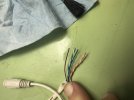
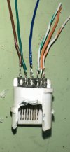
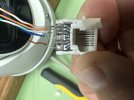
Camera side RJ-45 wire sequence

Coal_Cracker

Pulling my weight
Aug 21, 2022
116
216
USA
I have a camera with a bad terminator two of the blades are stuck down and I can't get them to spring back up. I tried it all, deox it, wire brushes, compressed air. As a last ditch effort to get the cam up and running again I'm going to put a new RJ-45 on and use an in line coupler to get it online again. Does anyone know the wiring sequence of the before I cut the bad end apart to see what goes where. I ask because if you look on the box there are two different wiring sequences on the box.IMG_3626.jpegIMG_3628.jpeg
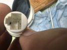
 
Educated guessing: The green and orange pairs are pretty self explanatory, other than you don't know if the original wiring was 568A or 568B. In a thread just this last week with the same question, the camera connector was wired with 568B. The brown and blue would be for power when the source uses POE Mode B (an injector), which you wouldn't even have to connect if using a Mode A source (a POE switch). Since both 568A and 568B are the same for the blue and brown pairs, the wire colors are a big hint (but not a guarantee) which pins they should go to. Each of the brown and blue would connect to both pins used by that color pair. Safest thing is to ohm out the wire-to-pin connections in the cut off connector.
 
Wow, was that the original factory wiring? If it was, what a hack job! It looks like they stripped the wire insulation with their teeth! :winktongue:
 
  • Like
Reactions: TonyR
Wow, was that the original factory wiring? If it was, what a hack job! It looks like they stripped the wire insulation with their teeth! :winktongue:
LOL. No, there was a plastic heat molded insulator there. I tried gently pulling the insulator off first before cutting it, as soon as I saw it was pulling the wire insulator with it I stopped and cut it off.
 
  • Like
Reactions: Smilingreen